 Motivation:
Mobility is an essential capability for any person who wishes to have an independent life-style. It requires successful execution of several tasks including path planning, navigation, and obstacle avoidance, all of which necessitate accurate assessment of the surrounding environment. For a visually impaired person these tasks may be exceedingly difficult to accomplish, and there are high risks associated with failure in any of these. Seeing-eye dogs and white canes are widely used for the purpose of guidance and environment sensing. The former, however, has costly and often prohibitive training requirements, while the latter can only provide cues about ones immediate surroundings. Human performance on information-dependent tasks, can be improved by sensing which provides information (e.g., position, orientation, or local geometry) and environmental cues via the use of appropriate sensors and sensor fusion algorithms. We are working on a novel indoor localization method for the visually impaired which has the potential for prodigious humanitarian impact. With the use of this localization aid, guidance and navigation algorithms can be implemented which will greatly increase the safety and overall mobility of its user.
Contribution:
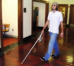
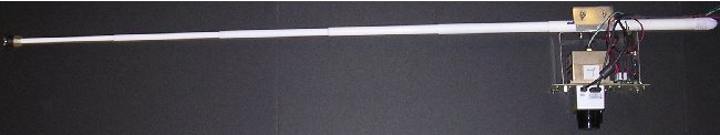
In our first paper, we present a hand held electronic aid capable of pinpointing its location within a building while the user holding it walks around. The purpose of this aid is to eliminate challenges that the visually impaired face on a daily basis. The most notable of these are navigating in unknown environments and safety concerns due to unseen and moving obstacles. Our vision is to mold this prototype with limited capabilities into a complete solution which is unobtrusive, reliable, and highly versatile; capable of performing intelligent tasks such as mapping, route planning, and interacting with its user by providing cues about the environment as well as guidance information.
Experimental Results:
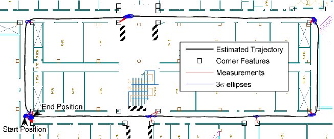
Below are the results of a test in an indoor environment on a closed loop of path length 130m. Twenty-one corners along this loop were known a priori from the building blueprints, and were used as features for position updates. While walking around, the user testing the cane swung it to-and-fro in a natural manner searching for obstacles which might lie in their path. The figure below shows the estimated trajectory super-imposed on the floor diagram. The striped regions in the figure depict obstacles such as couches and garbage cans, which are not detailed in the building blueprint. Additionally, some of the doors along the hallways were open, while others were closed. During testing there was a normal flow of pedestrian traffic through the hallways. All of the corners in the map are shown as boxes, and every measurement which was used to update the position estimate is marked with a line to the corresponding corner.
Video: [m4v]
Related Publications:
[C5]. J.A. Hesch, F.M. Mirzaei, G.L. Mariottini, and S.I. Roumeliotis, "A 3D Pose Tracker for the Visually Impaired," In Proc. of the IEEE/RSJ International Conference on Intelligent Robots and Systems (IROS), St. Louis, MO, Oct. 11-15, 2009 [details]
[C2]. J.A. Hesch and S.I. Roumeliotis, "An Indoor Localization Aid for the Visually Impaired," In Proc. of the IEEE International Conference on Robotics and Automation (ICRA), Roma, Italy, Apr. 10-14, 2007, pp. 3545-3551 [details]
Acknowledgements:
This work was supported by the University of Minnesota (GiA program) and the National Science Foundation (EIA-0324864, IIS-0643680).
 Motivation:
Cameras are utilized in a wide variety of
applications ranging from surveillance and
crowd monitoring, to vision-based robot localization.
In order to obtain meaningful geometric
information from a camera, two calibration
procedures must be completed. The
first is intrinsic calibration, that is, determining
the internal camera parameters (e.g.,
focal length, principal point, and skew coefficients),
which affect the image measurements.
The second is extrinsic calibration,
which is the process of computing the transformation
between the camera and a base
frame of reference. In a surveillance application,
the base frame may be the room or
building coordinate system, whereas on a
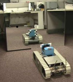
mobile robot, the base frame could be the robot-body frame (see example on the right).
Contribution:
Our objective is to determine the camera-to-base transformation from observations
of points whose coordinates in the base frame are known. We consider the most
limiting case, in which the known points do not lie within the camera's field
of view but can only be observed using a mirror. We maneuver a
planar mirror in front of the camera to provide multiple views of the points. In
our formulation, no prior information about the mirror motion or placement
with respect to the camera is assumed. The configuration of the mirror and
the camera-to-base transformation are treated as unknowns to be computed
from the observations. The main contribution of our work is an algorithm for
determining the camera-to-base transformation analytically, which requires a
minimum of 3 non-collinear points tracked in 3 images. Subsequently, we refine
the analytic solution using a maximum-likelihood estimator.
Related Publications:
[C4]. J.A. Hesch, A.I. Mourikis, and S.I. Roumeliotis, "Mirror-Based Extrinsic Camera Calibration," In Proc. of the International Workshop on the Algorithmic Foundations of Robotics (WAFR), Guanajuato, Mexico, Dec. 7-9, 2008 [details]
[C3]. J.A. Hesch, A.I. Mourikis, and S.I. Roumeliotis, "Determining the Camera to Robot-body Transformation from Planar Mirror Reflections," In Proc. of the IEEE/RSJ International Conference on Intelligent Robots and Systems (IROS), Nice, France, Sept. 22-26, 2008, pp. 3865-3871 [details]
[R2]. J.A. Hesch, A.I. Mourikis, and S.I. Roumeliotis, "Camera to Robot-body Calibration Using Planar Mirror Reflections," University of Minnesota, Dept. of Comp. Sci. & Eng., MARS Lab, Tech. Rep. 2008-001, July 2008. [details]
Acknowledgements:
This work was supported by the University of Minnesota (DTC), and the National Science Foundation (EIA-0324864, IIS-0643680).
I have contributed to several other research endeavors at the Multiple Autonomous Robotic Systems (MARS) Lab. Feel free to visit our projects page for more information.